Arduino as an ISP for AVR Microcontrollers (Atmega32)
Published on July 03,2019
To begin with, what in the world is an ISP and why should you care? In-system programming (ISP), is the ability of some embedded devices e.g microcontrollers, to be programmed while installed in a complete system, rather than the chip being programmed prior to installing it into the system. For more information on ISP, check out Wikipedia.
A discourse of “embedded systems”
Whether your sound mind is aware of it or not, or you just decide to ignore the sure fact; you are in possession of or have used an electronic device. A phone, an ATM machine, a radio, a laptop computer, a gaming console, a smart TV, a smart card reader at the supermarket or at your local bank's agent a microwave oven and many more. One thing, for sure, is that they all have a computer within them. The computer is so small relative to its housing that technocrats saw it fit to refer to them as “embedded”. Since the computer can allow for input, processing, and output, it is worth renaming it to a system, thus the term “embedded system.” The embedded systems come in a myriad of ways; as Programmable logic devices (PLDs), microcontrollers, etc. In relevance to today’s topic, some of these embedded systems come preprogrammed to do specific functionalities before they are installed in a complete system, whereas others come as a bare chip ready to be programmed and reprogrammed by you. The latter category exposes the ISP characteristics, and we will go with microcontrollers.
Why Arduino
Programming an embedded system involves writing a computer program in the right language, say assembly, C or C++, compiling the code with the appropriate compiler to generate an appropriate hex file for the intended hardware (Atmega32), then uploading the code using an ISP programmer. For writing and compiling the code, one might use Atmel studio or MPLABX IDEs. When it comes to uploading the code, however, one needs to buy an ISP programmer like the ones pictured below (pickit3, USBtinyISP AVR):
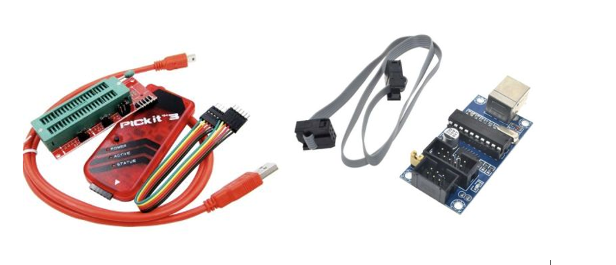
These are, however, usually expensive and not readily available to many. Arduino board, on the other hand, is. Other than being a prototyping platform, one can also use Arduino as an ISP for AVR boards (a family of microcontrollers manufactured by Atmel, recently acquired by Microchip).
Requirements
- Arduino UNO
- Atmega32 Chip
- 1x16 MHz Crystal Oscillator (Optional)
- 2x20 picoFarad Capacitors (Optional)
- Breadboard
- 4xLight Emitting Diodes(LEDs)
- 4x470 Ohm Resistors
- Arduino IDE
- 9V battery & 7805 Voltage regulator (Optional)
- Male-Male jumper cables
- You have downloaded and Installed the Arduino IDE.
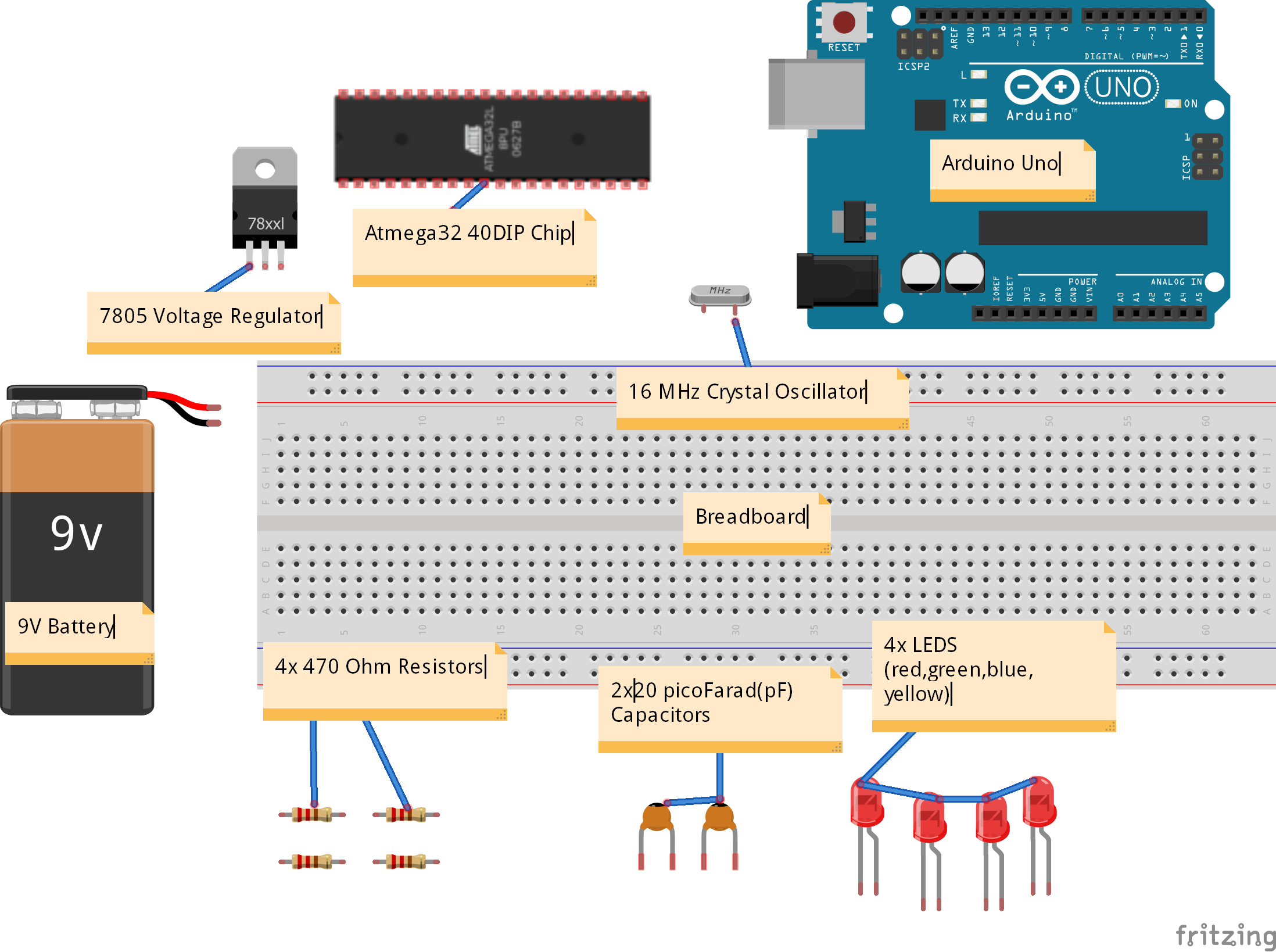
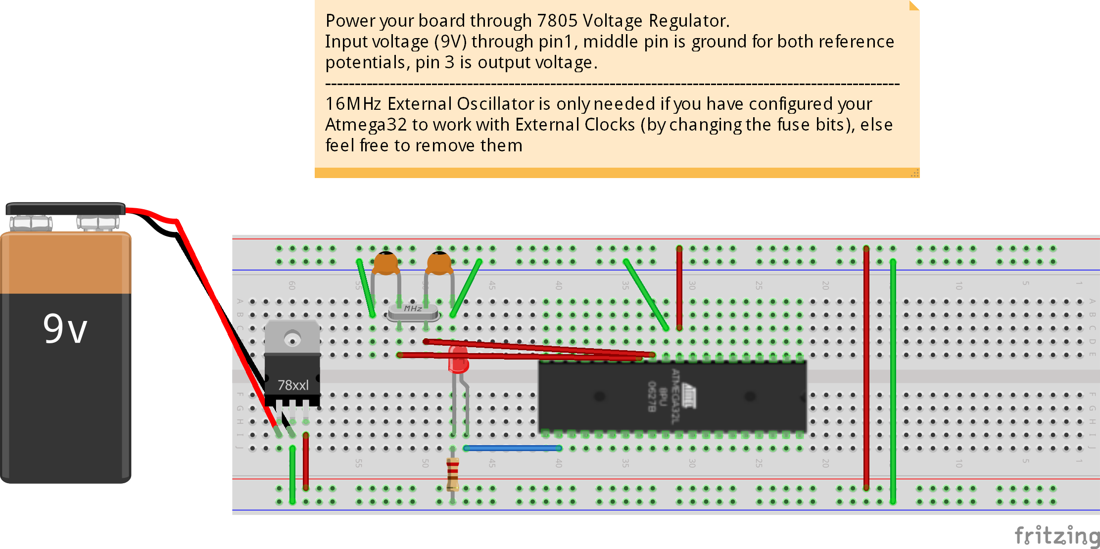
Hardware Setup
Connect the circuit as shown and described below. You can decide to omit the crystal oscillator-capacitors part. This will become relevant in “uploading code section”.

Pins 10 and 11 of Atmega32 are connected to 5V power and ground respectively. The array of LEDs to the right are for indicating that the Arduino as ISP is working as expected. They will blink appropriately depending on the status of the communication. More on this later. The blue-wired connections are for uploading the code to the microcontroller, while the rest of the circuitry is the bare working microcontroller circuitry. Ensure your Arduino is connected to your computer.
Software setup
This is practically the most important part of the circuitry setup. It enables your computer software to communicate with Atmega hardware. You can also satisfyingly claim that it is the kernel of your circuitry that talks to the device drivers in Your Atmega32 to run your code. So carefully tread in this minefield. It generally takes two minutes to complete.
1. Download the following zipped file (2.61MB) and extract it to your desktop. The file consists of Atmega32 Datasheet, boards.txt file, pins_arduino c header file, HardwareSerial C++ header file.
2. Adding Core Board definitions. This section allows your IDE to be able to compile programs targeting your specific Atmega32 board.
- Go to the directory where your Arduino IDE is installed. Mine is “C:\Program Files (x86)\Arduino\”. Change directory to “hardware\arduino\avr”
- Replace the "boards.txt" file with the one you unzipped from the downloaded file. The file contains all the default board definitions that come with Arduino, plus our new Atmega definitions. If you feel like keeping your original board definitions intact, then kindly copy from our boards.txt file, the atmega32 section(right after Arduino Yun board definitions), then append them in your original boards.txt. If you are not allowed to make the changes then open up your original boards.txt file in a text editor of choice e.g. sublimeText, paste the desired changes and then "save as" to the desktop, after which you copy and then paste the file to the aforementioned directory ("REPLACE THE FILE").
3. Adding new board pins definitions. This header file tells your compiler if you are using Arduino IDE to code in microC/Embedded C for the board (I am), to generate an appropriate .hex file that has the pin configurations that corresponds to your board, say Atmega32. It educates the IDE about your board's pin configurations
- For Windows systems, go to the directory “C:/program files (x86)/Arduino/hardware/arduino/avr/variants”
- In the directory, create a folder called “mega32” with the small letters
- In the directory "mega32", copy and paste the header file "pins_arduino.h" from the unzipped file you downloaded.
4. Updating the hardware serial library
- For Serial library to work properly, the following changes must be made to the file HardwareSerial.cpp. Head over to the directory “..\arduino\hardware\arduino\avr\cores\arduino\HardwareSerial.cpp”
- Simply replace the HardwareSerial.cpp source file with the one you downloaded or conservatively replace:
#if defined(__AVR_ATmega8__)
    config |= 0x80; // select UCSRC register (shared with UBRRH)
#endif
with:
#if defined(__AVR_ATmega8__) || defined(__AVR_ATmega32__) || defined(__AVR_ATmega16__)
    config |= 0x80; // select UCSRC register (shared with UBRRH)
#endif
Blinking an LED embedded C example
With the integrity of your hardware setup (circuit) intact, fire up Arduino IDE. Click File, examples, ArduinoISP, ArduinoISP as shown below. Upload the program to Arduino by navigating to the sketch menu and clicking upload
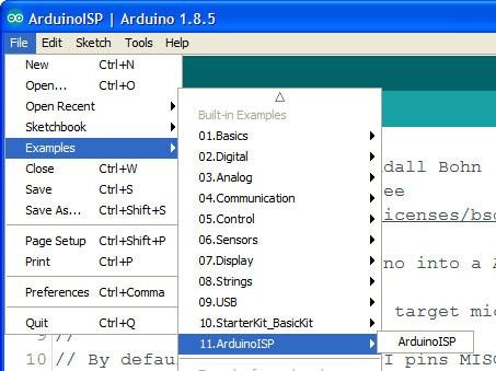
If everything went well, you should see the LED you connected to pin 9 of Arduino fading in a heartbeat manner. This means that your Arduino board is now an ISP programmer and can load code to your Atmega32 board.
A note on bootloader
You do not need to burn a bootloader program to your chip. As explained in the official datasheet, Atmega32 has an on-chip ISP Flash and an On-chip Boot program running on the AVR core. These allows the program memory to be reprogrammed in-system through a Serial Peripheral Interface (SPI).
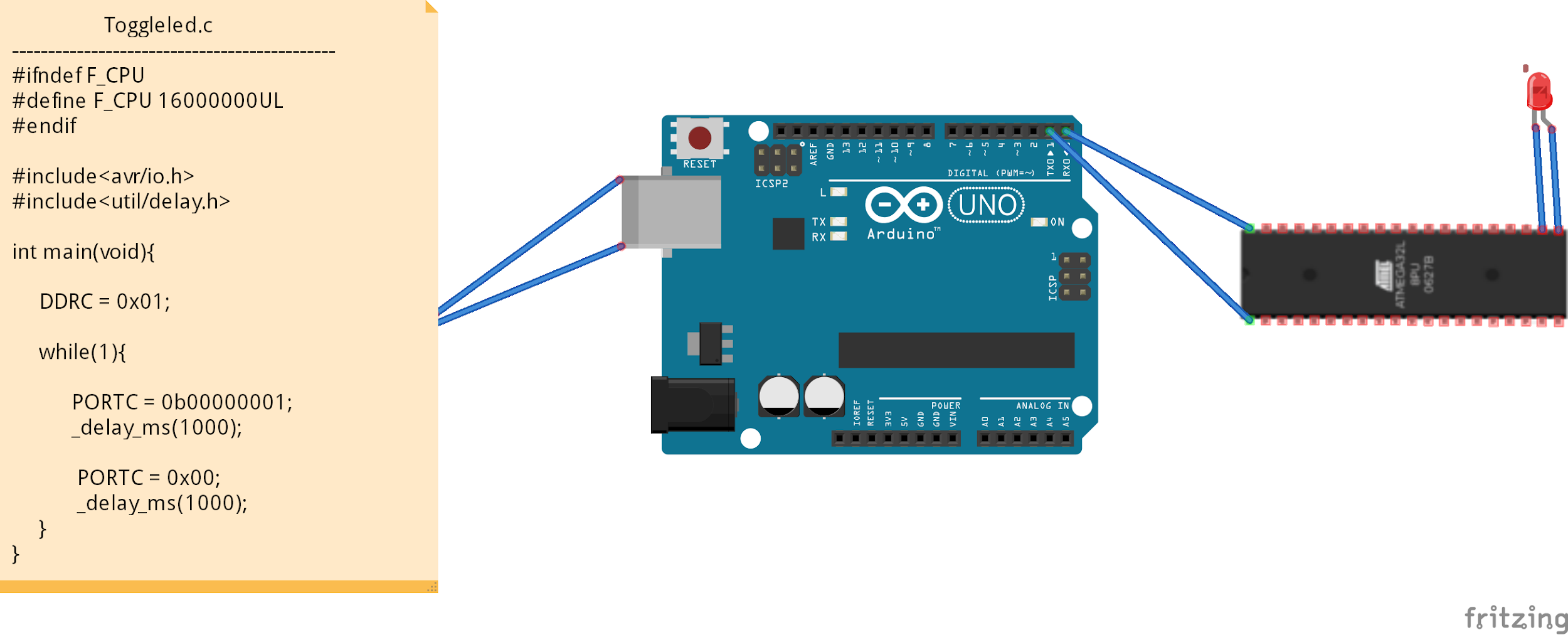
Now let’s write a code to be uploaded to our Atmega32 board to blink up our LED connected on pin 22 (PC0). Refer to the datasheet downloaded to verify the right pin. If you decide to configure your board to use the external 16Mhz clock, then the program may slightly look different in the Macros section as shown in the introductory picture.
	#define F_CPU 1000000UL  //defining the frequency of the CPU as 1MHz

	#include<avr/io.h> //Including avr’s input-output header library
	#include<util/delay.h> //Including utilities for performing delay functions

	int main(void){
		DDRC = 0x01;   //Declaring pin 22 (PC0) as output

		while(1){   //creating a forever loop, that our microcontroller may not be idle

			PORTC = 0b00000001;  //Turning PC0 high, turning our LED on
			_delay_ms(1000);  //maintain the on status for one second

			PORTC = 0x00; //Turning off all port C’s including PCO (Our LED)
			_delay_ms(1000); //Maintain the off status for 1 second

		}
	}
Compiling and Uploading the code
To begin with, head over to the “Tools” tab and select the appropriate board. Select "ATmega32-1 Mhz” board if you are using the default clock configurations. This also means in your circuit you don’t connect the external crystal oscillator part. In the same tools tab select the appropriate programmer, select “Arduino as ISP” and NOT “ArduinoISP”. Finally, select the COM port through which your Arduino is connected. First, ensure your Arduino is connected to your PC and then click on the COM port. Once everything is done, click on the “verify” button (the check/tick mark button). When the save as window appears, type the name of the file and do not change the file extension. You can save the file as “toggleled.c”, however. Wait for everything to compile successfully till you see the white text “...sketch uses…”.
You are now ready to upload the code to your ATmega32 board. Take it slow here. Go to “sketch” tab and click on “Upload Using Programmer”. If you don’t click on this, and instead click on the normal upload, your code will go to Arduino board instead of your ATmega32 board. If everything went well, your status LEDs should blink rapidly in order and your LED connected to PC0 should blink after every second. Now you can plug out your Arduino circuit and connect the minimal power circuitry as below to show that you ATmega32 board is now independent of Arduino and that it runs you toggle led code. Remember that you can always remove the crystal oscillator circuitry if you are using the default 1MHz internal clock circuitry. I recommend this default configuration. You can always request an article on how to turbo-charge your
Atmega32 to use an external 16MHz clock or its internal 8 or 16MHz clocks.
Conclusion
I love electronics so much that I would appreciate seeing you go beyond the Arduino world and programming the microcontroller itself. When I peer keenly into the future, everything including your precious cows would soon have computers embedded inside them for tracking and health monitoring reasons. Everything, including your beloved flower garden, will surely have a taste of what an embedded system can do. But more computers and embedded systems mean more embedded programmers will be needed. It is a world so unpopular yet vast and commonplace like the toddler AI, mainly because it's often technical and left for the technocrats. Albeit I have a little background in electronics, if I can do it, then so can you. It only takes, as my brother would put it, “consistency”, and the love for electronics. Have a nice read, and feel free to request any more articles on this subject. it would be my pleasure.